Ford 351 Windsor Engine Guide
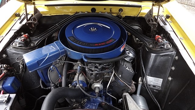
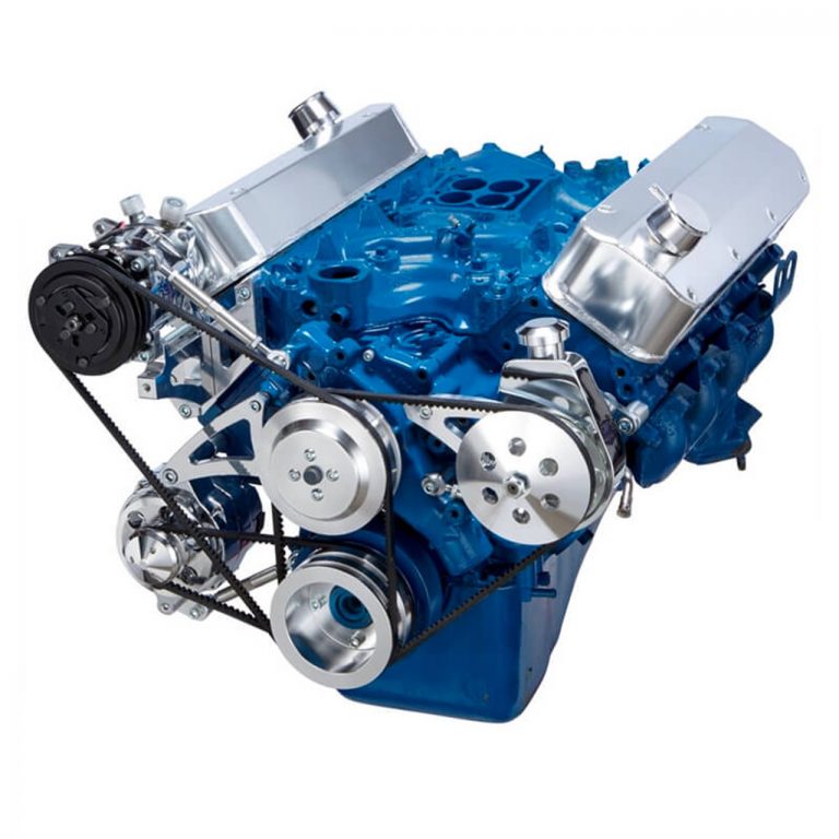
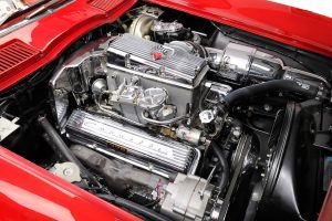
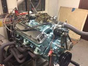
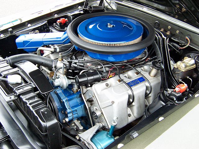
The Ford 351 Windsor is the largest displacement engine in the Ford Windsor engine series. It was introduced in 1969 to fill the gap between the 302 and 390 V8 engines. Ford’s ultimate goal was to create an engine that was versatile and usable in a number of applications, which is exactly what the 351W…
Latest Muscle Car Content
Search by Manufacturer

List of Muscle Cars

Classic & Modern Muscle Cars
Muscle Car History & Guides
Muscle Car Club provides a wealth of information, history, and general education around classic muscle cars and engines. Additionally, we cover buying guides and performance modifications for modern day muscle cars.
We aim to provide the best classic muscle car information on the internet, with a focus on accuracy, honesty, and quality.

Muscle Car History Guides


Latest Content
Ford 351 Windsor Engine Guide
The Ford 351 Windsor is the largest displacement engine in the Ford Windsor engine series. It was introduced in 1969 to fill the gap between the 302 and 390 V8 engines. Ford’s ultimate goal was to create an engine that was versatile and usable in a number of applications, which is exactly what the 351W…
Ultimate Ford 429 Engine Guide
The Ford 429 is one of the most iconic big-block V8s that Ford has ever produced. Between its introduction in 1968 and its discontinuation in 1998, the 429 powered everything from the Mustang to the Ford F-Series. In addition to the base passenger model, Ford eventually realized the massive potential of the 429 and created…
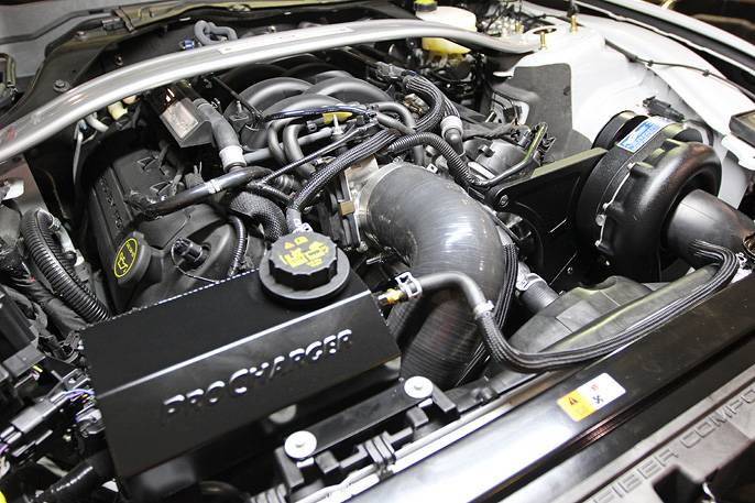
Shelby GT350 5.2 Voodoo Engine Guide
The Ford 5.2 Voodoo is a truly unique muscle car engine. The 5.2L V8 utilizes a flat-plane crankshaft and is able to rev to 8,250rpm; it’s good for 526 horsepower and 429 lb-ft of torque. That may not sound overly impressive compared to the 760hp GT500 or even the base 5.0 Coyote with its 480…

Ford 460 Engine Guide
The Ford 460 V8 is the largest displacement engine in the Ford 385 engine series. As the replacement for large displacement Ford FE and MEL engines, the 460 started out as the go-to engine option for big-body luxury cars like the Lincoln Continental. Later in its production cycle, the 460 found a home in utility…

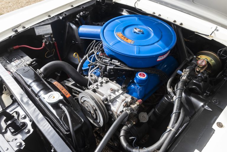
Best Ford 289 Engine Upgrades
The 289 is a staple of the muscle car era, appearing in many of Ford’s seminal models including the first generation Mustang, Fairlane, and, perhaps most importantly, the GT40. That isn’t even including the number of Shelby-specific applications as well. Helped immensely by its impressive legacy, the Ford small-block is one of the most famous…
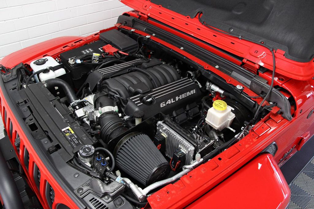
6.4L HEMI Engine Guide
The 6.4L HEMI represented a new leap forward in the GEN III HEMI lineup, following the 6.1L which had quite the reputation of its own. From 2011 to 2021, the 392 HEMI, as it was called alternately, powered the bulk of Chrysler’s performance lineup, including most SRT8 models, SRT SUVs, and a number of RAM…
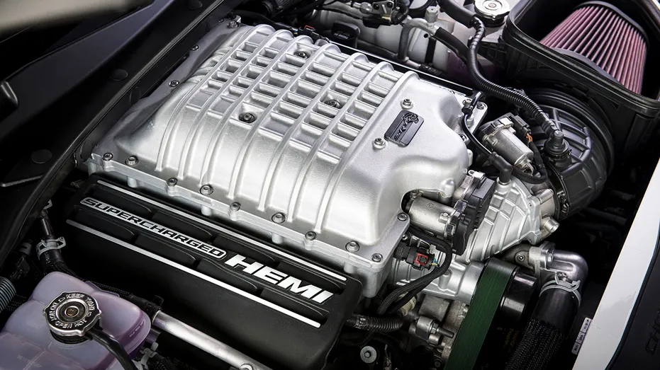
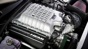
6.2 HEMI Hellcat Engine Guide
The 6.2L HEMI Hellcat was first introduced in 2015 as a supercharged extension of the Gen III HEMI engine family. Powering both Challenger and Charger models with the same Hellcat namesake, the engine quickly gained the reputation of being the top dog of the American muscle scene and could back it up on the strip. …
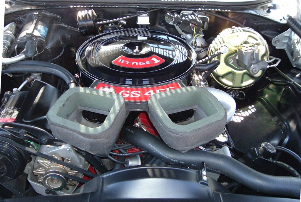
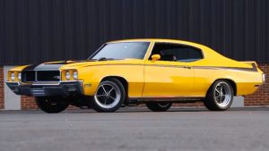
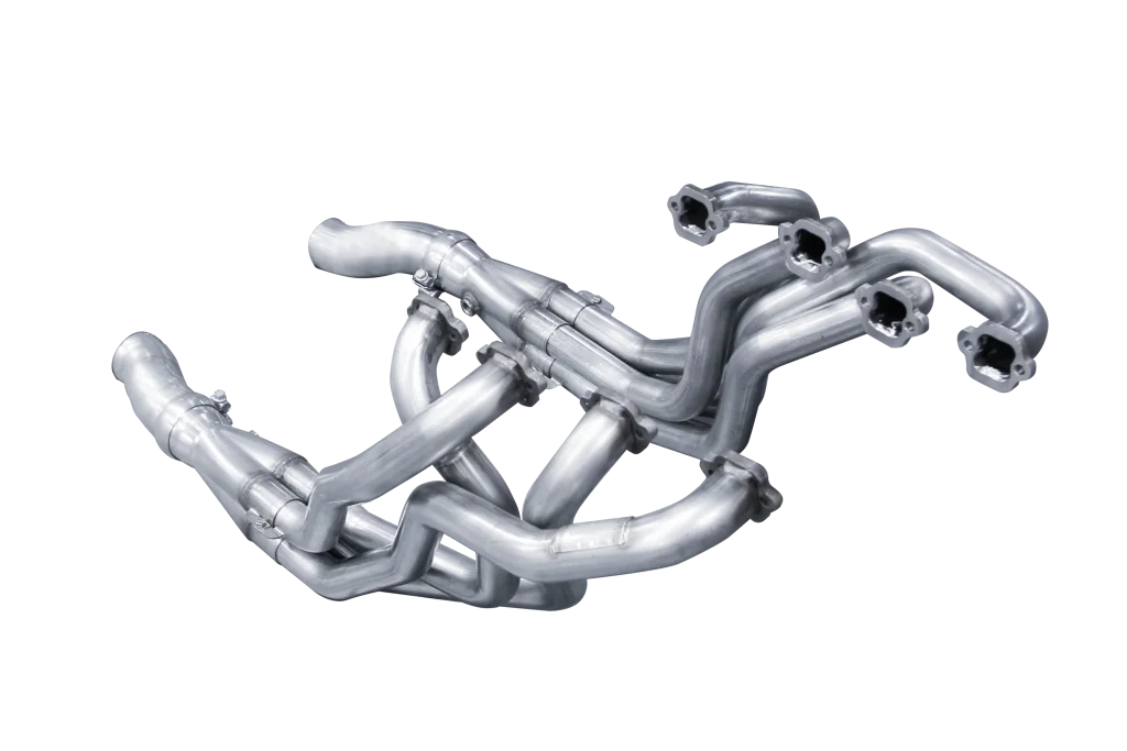
Best Buick 455 Upgrades
Long known as one of the top muscle engines of all time, the Buick 455 V8 is still very popular in the 2020s. From the factory, the big-block V8 produced as much as 370 horsepower and 510 lb-ft of torque, and it was one of the fiercest competitors of the 1970s. Today, many enthusiasts still…
Top Ford 302 Performance Upgrades Guide
For those looking at the top Ford 302 performance upgrades, it’s hard to beat adding a cold air intake, long-tube headers, MSD ignition, and a larger carburetor. Ford produced the 302 V8 from 1968 all the way until 2001, and it powered all kinds of different vehicles. They have proven extremely popular over the years…